As we drive our workflow to zero photo editing, we tested the Canon Rebel T5 & T6 in our scanning process. The testing was done on our light tower with a varying number of shiny items on the light panel. The Canon T5 & T6 test results yielded standard deviation of .06mm in our testing (attached).
Visual/Auditory Tutorial:
Written Tutorial:
Step #1
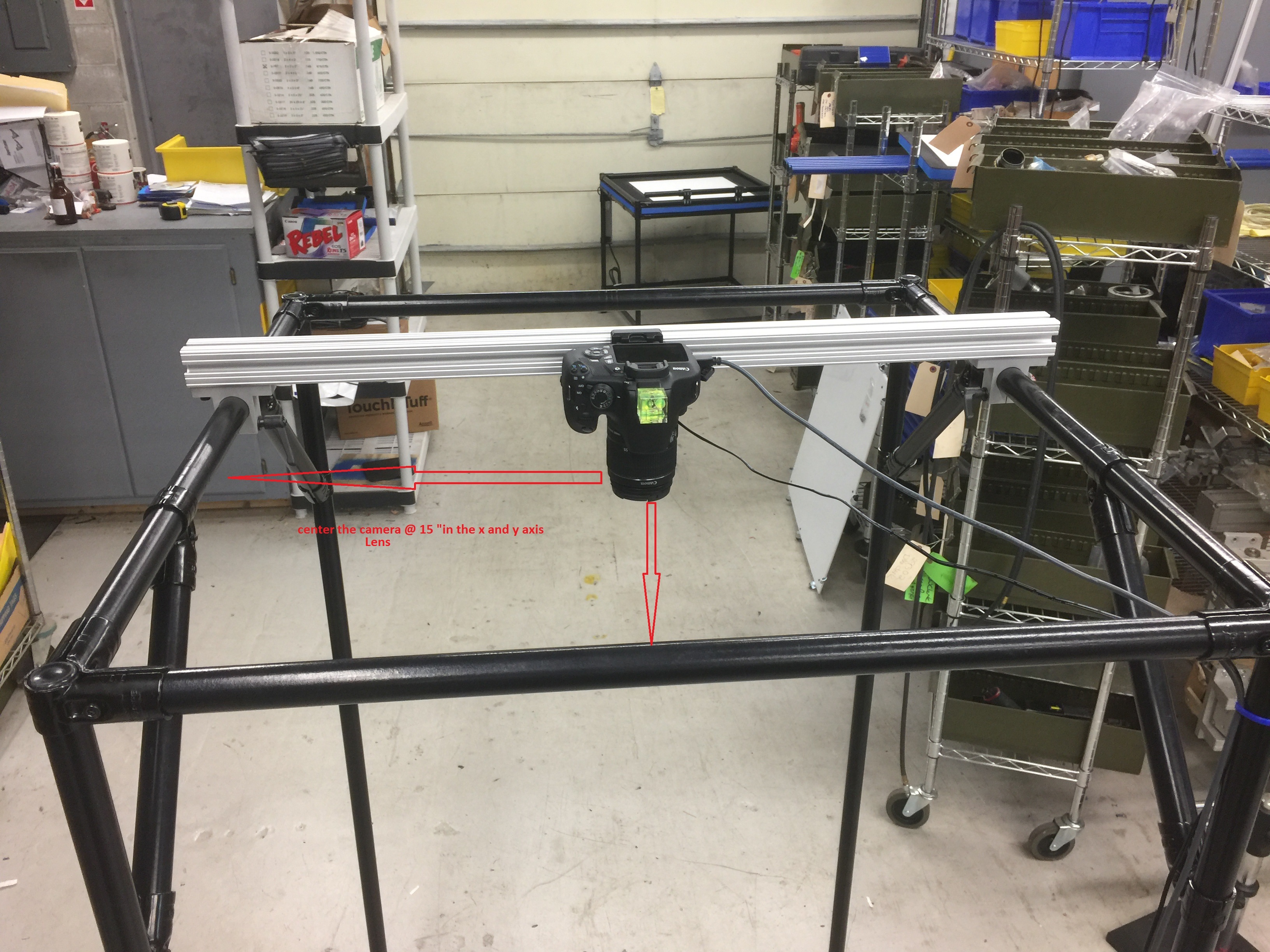
Tilt the top section of the light tower down to 45 degrees and remove the light curtain if necessary.
Step #2:
The light tower is shipped with the cross bar and camera mount positioned for the camera to be centered over the light panel. The camera is also shipped with the mounting plate attached. You should be able to simply snap the camera into the bracket and lock it in place. If you are retrofiring the aluminum cross bar and camera mounting plate to an older light tower take the time needed to correctly position the mounting plate before proceeding.
Step #3
Make sure the camera is set to the factory default settings. If you are not sure if the camera settings are at the factory default go to the menu and scroll to Clear Settings and activate the function.
Here is a video showing how to clear all settings and get the Camera back to default:\
Step #4
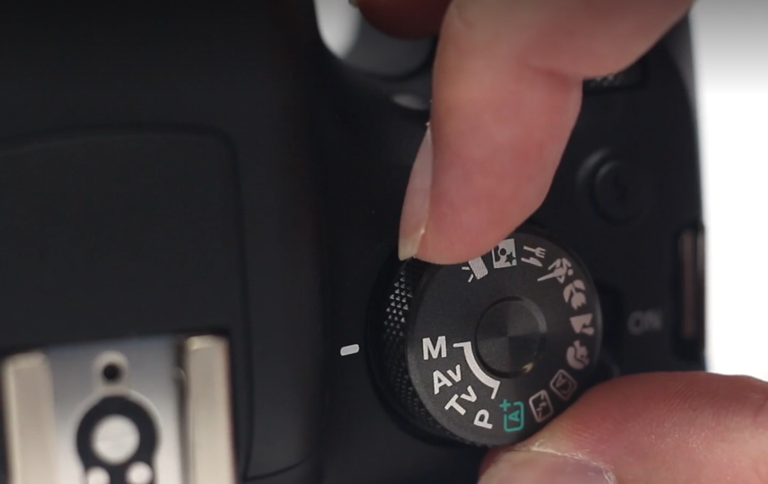
Set the settings wheel on the T5, T6, or T7 Camera to M for Manual.
Step #5
Set the zoom on the camera between 33-40 mm
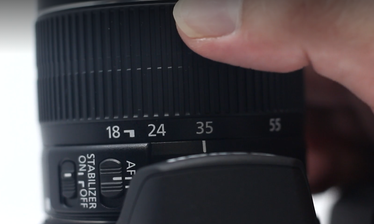
- The focal length on the lens should be between 33 and 40. A focal length setting of 39 or 40 zooms the picture in to a greater degree which in-turn results in the frame of the light tower taking up more of the photo which is preferred. The larger the frame is in the photo the more pixels are inside the frame which increases the scan board numbers in the testing of the photo when scanning (see scanning article for details).
- A focal length of 39 or 40 results in maximum zoom requires nearly perfect camera positioning based on the position of the camera in the light tower. If the camera is out of position at maximum zoom the frame of the light panel may not be included in the photo which is unacceptable.
- A full length of 33 allows for more forgiveness in the camera position, however the frame of the light panel is smaller resulting in scan board test results of 46 - 47 which is on the very low end of the acceptable range. We do not recommend setting the camera below a focal length of 33 and encourage to take the time needed to position the camera perfectly to achieve maximum zoom.
Step #6
Install the battery eliminator in the battery slot of the camera and plug it into the power strip provided with the light tower and turn the camera on. From this point forward you can turn the camera on and off at the power strip. There is no need to reach up to the camera to power it on or off.
 |
 |
Step #7
The best time to tie-wrap the power and USB cables to is the first time the camera is put into position in the light tower. If you purchased a pre-assembled light tower, these cables will be tie-wrapped in place for you. If you are assembling the light tower yourself or retrofitting the hardware or camera to an older light tower you will need to tie-wrap the cables at this step in the process.

Step #8
The computers shipped with the light tower have the canon image capture software factory installed. If you did not purchase a computer from OSAAP the software was shipped with the light tower on a memory stick and must be installed on each computer that will be used with the light tower. Once you are sure the canon software is installed on your computer connect the camera to the 15' USB cable provided with the light tower.
Step #9
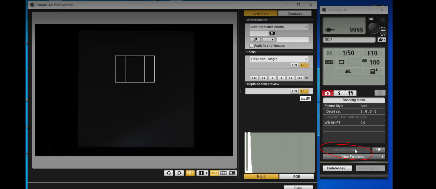
Connect the camera to the computer with the usb cable provided and open the canon live image capture software. Check the camera settings before proceeding, they should be as follows:

Step #10
Click the LV button in the top left corner of the digicam software to activate "Live view."
Step #11
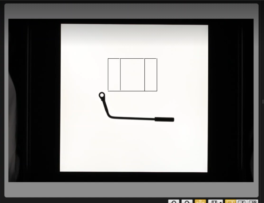
Manually zoom the camera to the maximum point possible keeping in mind that the frame of the light panel must be in the photograph, and snap a test photo.
Step #11
Open OSAAP's BlueShadow CAD design software which is pre-installed on computers shipped with the light tower. If you are using your own computer you need to download the software from the OSAAP website. Then follow the instructions in the Scanning Images training KB article (located in related articles). The software tests the photo before inserting it onto the CAD work-space. The test results of your photo should look like the photo below.
The scan board result is directly related to the focal length of the camera. The 62% shown here resulted from the focal length of 39. Our testing shows scan board numbers of 46% at a focal length of 33. Try to position the camera well enough to get scan board numbers in the mid 50's at a minimum.